3D modelling
Openscad
Using openscad was rather easy because I feel like its less confusing to model an object through writing code instead of simply sketching... which is not a popular opinion.The following details the procedure that I have followed into modelling a possible model for my final project. The code ended up to be a bit messy and could have been much shorter that what it currently is. I have used a manual on wikibooks on how to use the software.
https://en.wikibooks.org/wiki/OpenSCAD_User_Manual/The_OpenSCAD_Language
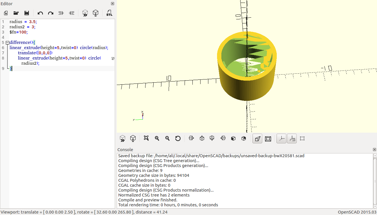
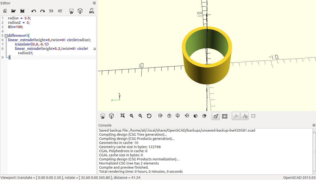
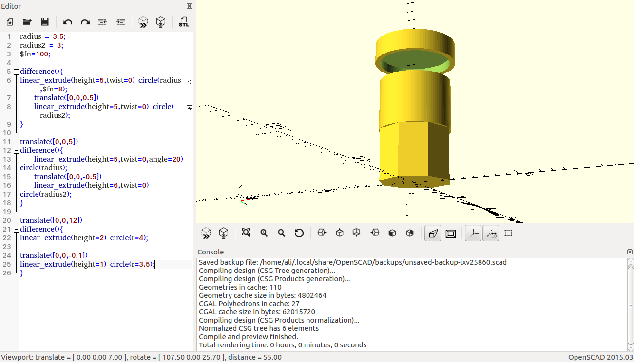
I have faced some problems when using the difference command. An example of the problem faced is shown below, where the issue occurs when the two objects that are subtracted from each other start/end at the same point. The result is that the common start/end point will contain some residue from the original object. The solution to this issue was simple, all I did was to increase the size of the objects on the "minus" side of the difference by a small amount, which removes the residue.
Residue problem
Possible final project design
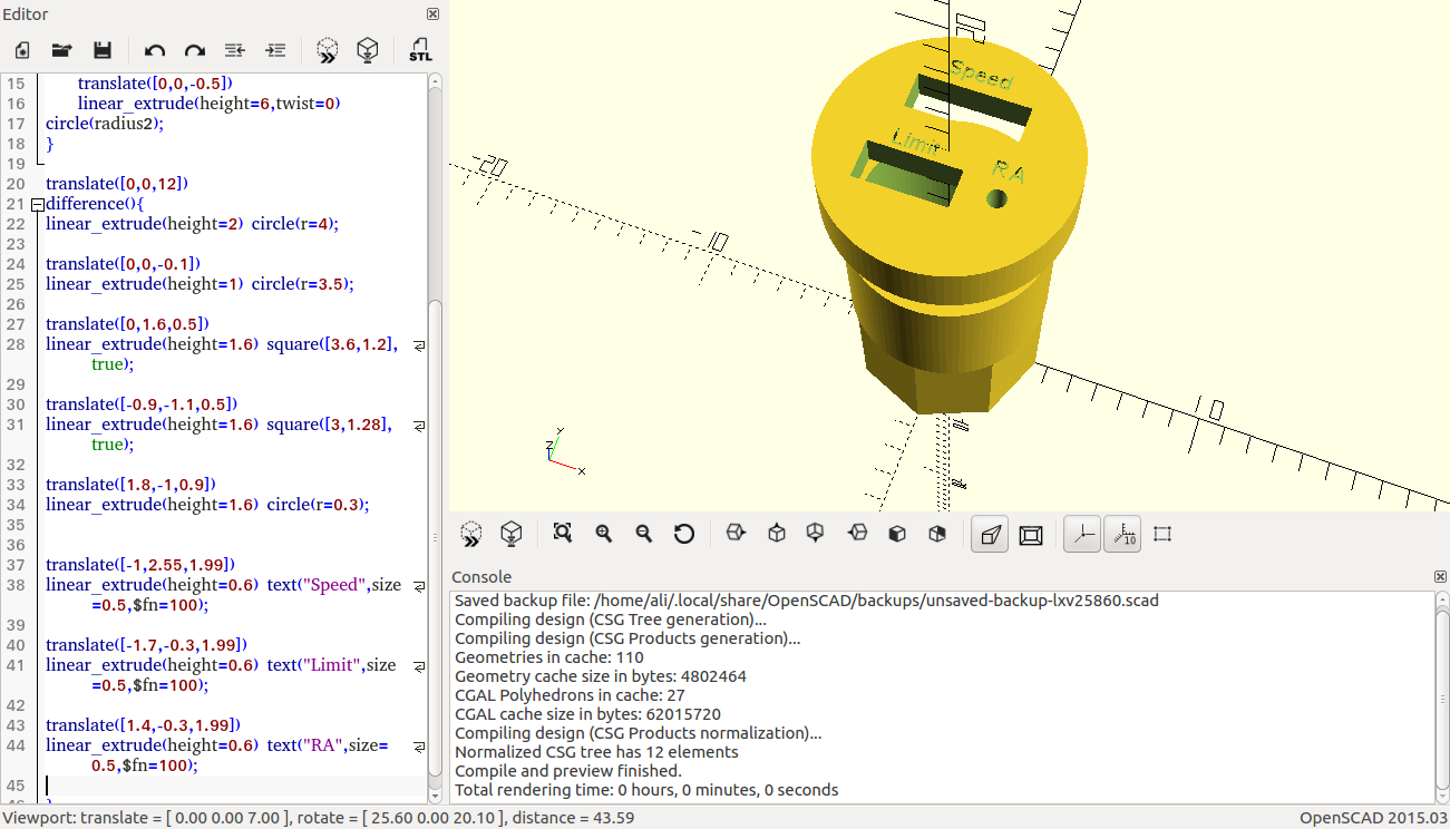
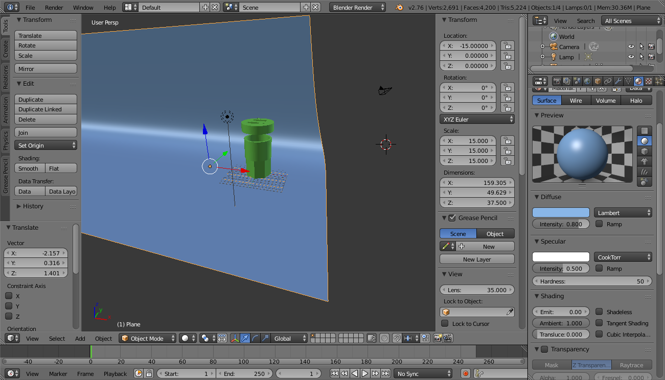
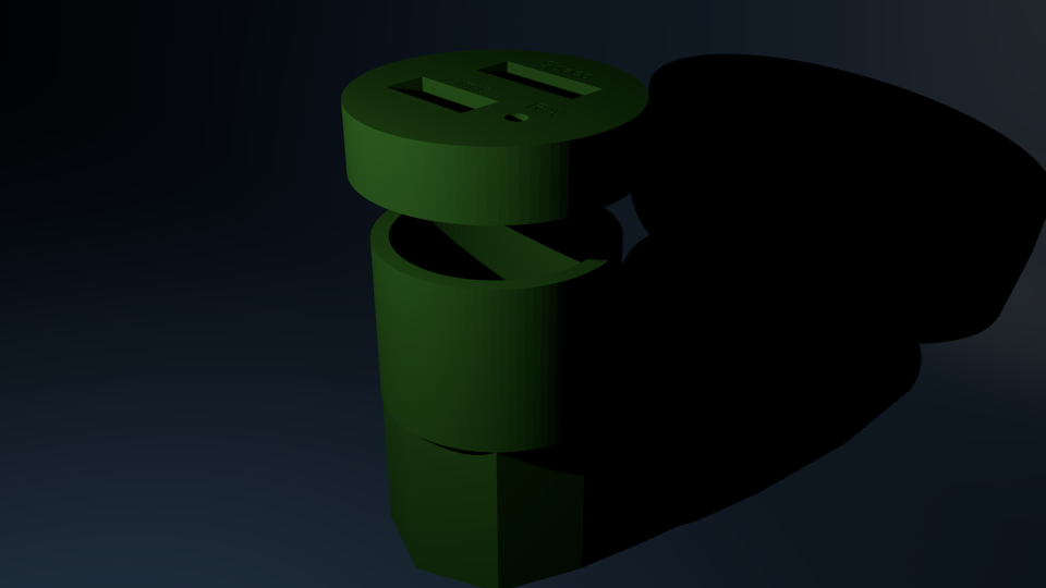
I have designed the outer case of my final project, which is supposed to fit in a car's cup-holder. The design is parametric (but might require some minor tweaks later), and the scale is 1=1cm.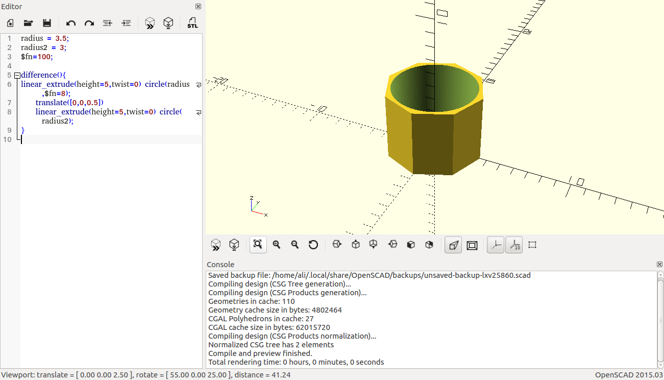
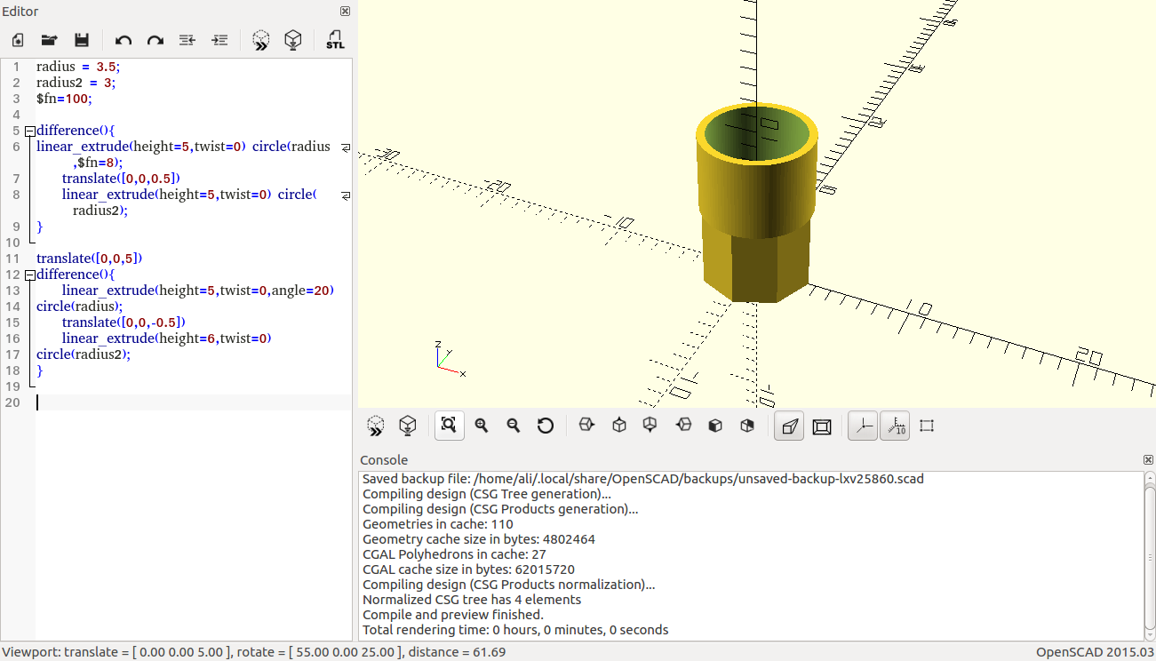
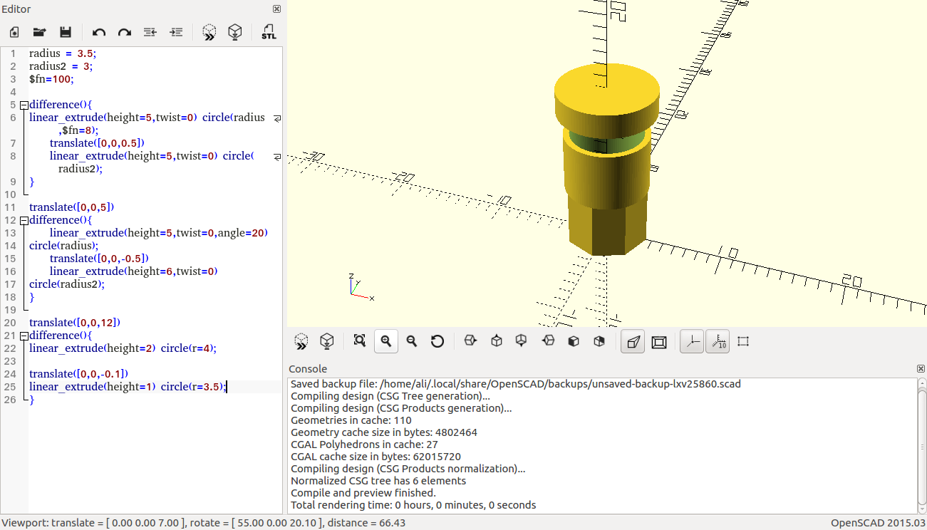
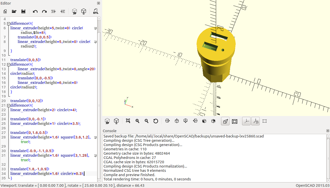
The final result
radius = 3.5;
radius2 = 3;
$fn=100;
difference(){
linear_extrude(height=5,twist=0) circle(radius,$fn=8);
translate([0,0,0.5])
linear_extrude(height=5,twist=0) circle(radius2);
}
translate([0,0,5])
difference(){
linear_extrude(height=5,twist=0,angle=20)
circle(radius);
translate([0,0,-0.5])
linear_extrude(height=6,twist=0)
circle(radius2);
}
translate([0,0,12])
difference(){
linear_extrude(height=2) circle(r=4);
translate([0,0,-0.1])
linear_extrude(height=1) circle(r=3.5);
translate([0,1.6,0.5])
linear_extrude(height=1.6) square([3.6,1.2],true);
translate([-0.9,-1.1,0.5])
linear_extrude(height=1.6) square([3,1.28],true);
translate([1.8,-1,0.9])
linear_extrude(height=1.6) circle(r=0.3);
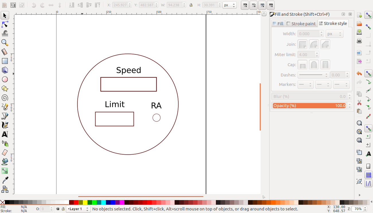
translate([-1,2.55,1.99])
linear_extrude(height=0.6) text("Speed",size=0.5,$fn=100);
translate([-1.7,-0.3,1.99])
linear_extrude(height=0.6) text("Limit",size=0.5,$fn=100);
translate([1.4,-0.3,1.99])
linear_extrude(height=0.6) text("RA",size=0.5,$fn=100);
}
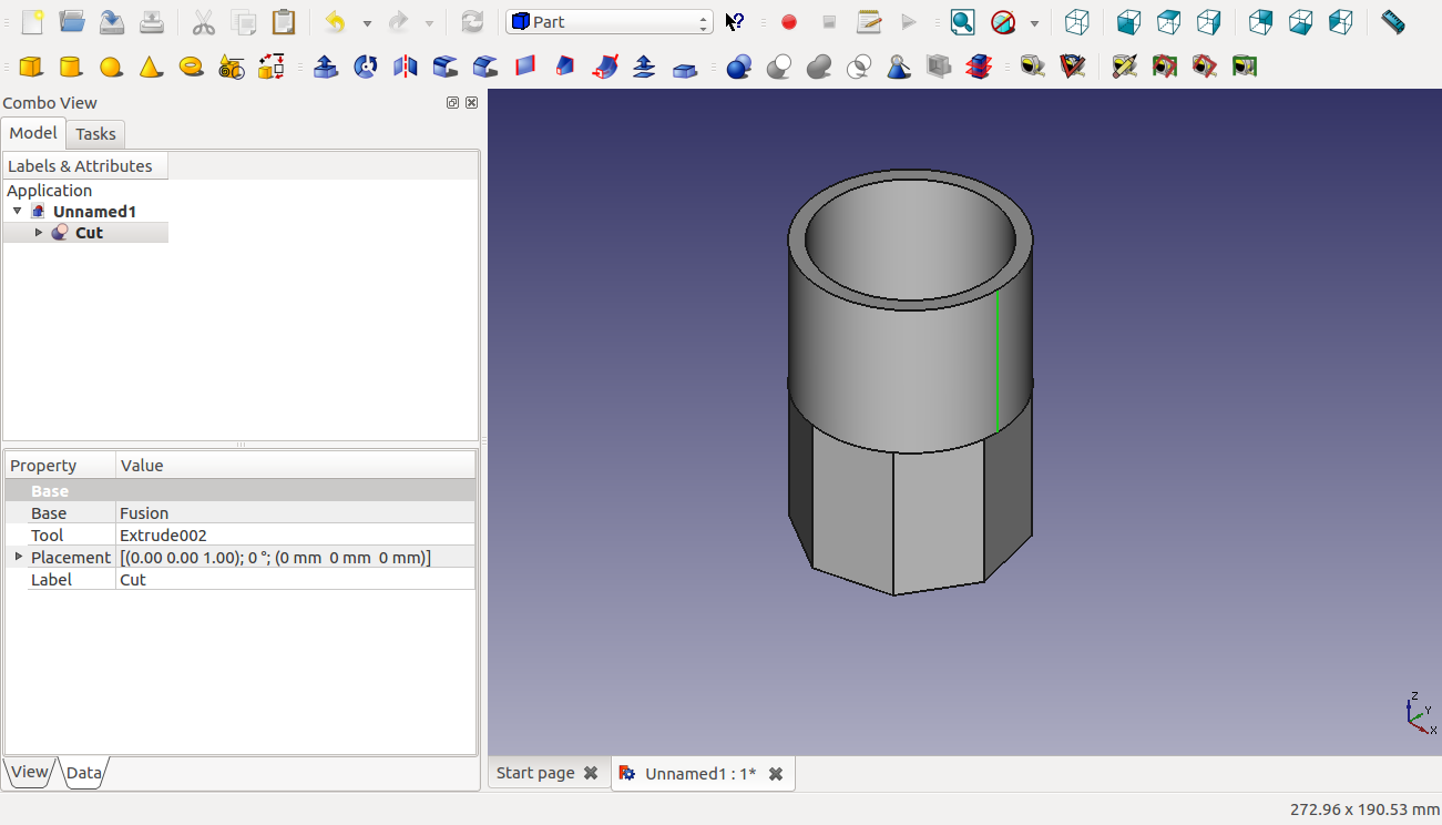
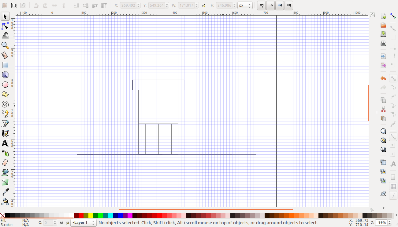
FreeCAD
In FreeCAD, I have designed almost the same model as the one in openscad, but without the cup.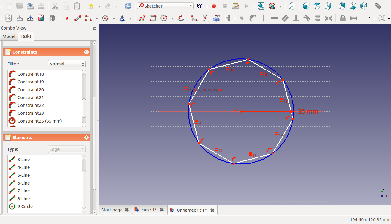
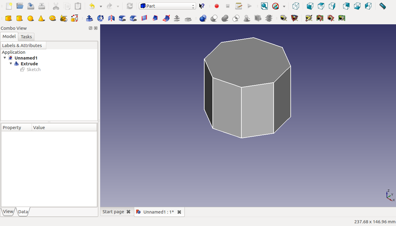
The final result